I occasionally hear people talking about a 'many-to-many' relationship as if it were a valid construct, but anyone who knows anything about database design knows that there is no such animal. Here I will explain what a 'many-to-many' relationship really means and how to deal with it.
A 'many-to-many' relationship is where many occurrences of ENTITY 'A' can be related to many occurrences of ENTITY 'B'. This is often drawn as a Entity-Relationship (E-R) diagram as shown in figure 1:
Figure 1 - a Many-to-Many relationship
|
|
|
The only valid relationship in any DBMS that I have come across is a 'one-to-many', so a better way of defining a 'many-to-many' relationship would be as a reciprocal pair of 'one-to-many' relationships as shown in figure 2:
Figure 2 - a pair of One-to-Many relationships
|
|
|
By a reciprocal pair of relationships I mean that:
However, this is still an invalid construct as it is not possible to link two entities together in such a manner. The answer is to introduce an intermediate entity which will act as the 'many' in both relationships. This is sometimes known as a LINK, INTERSECTION or XREF (cross-reference) entity, and is shown in figure 3:
Figure 3 - using an intermediate LINK entity
|
|
|
|
|
It should be obvious that the LINK entity should contain a foreign key to Entity 'A' as well as a foreign key to Entity 'B', but where some people fall down is in the definition of the primary key. A common mistake comes from those people who blindly follow the rule that every entity must have its own technical primary key, which results in Design 1:
Design 1 - not good
| primary key | foreign key | foreign key |
|---|---|---|
| PKEY_LINK | PKEY_A | PKEY_B |
| 1 | A1 | B6 |
| 2 | A3 | B27 |
| 3 | A3 | B42 |
| 4 | A9 | B27 |
Note that this shows more than 1 occurrence of 'A3' and more than 1 occurrence of 'B27'.
I dislike this particular design for the following reasons:
Design 2 shows how the last two problems can be avoided by the creation of a candidate key:
Design 2 - better, but still no cigar
| primary key | candidate key | |
|---|---|---|
| foreign key | foreign key | |
| PKEY_LINK | PKEY_A | PKEY_B |
| 1 | A1 | B6 |
| 2 | A3 | B27 |
| 3 | A3 | B42 |
| 4 | A9 | B27 |
This design is still inefficient because it requires a separate index for both the primary key and the candidate key. Even worse would be an index on each of the two foreign keys. A more efficient solution would be to drop the separate technical key entirely and change the candidate key into the primary key, as shown in Design 3:
Design 3 - my favourite
| primary key | |
|---|---|
| foreign key | foreign key |
| PKEY_A | PKEY_B |
| A1 | B6 |
| A3 | B27 |
| A3 | B42 |
| A9 | B27 |
Here we see that the primary key for the LINK entity is a combination of the foreign (primary) keys for the two related entities. Note that it is not necessary to have a separate index for PKEY_A as it is already provided by being the leading portion of the primary key. An index for PKEY_B would only be necessary if there was a requirement to access the data via this path.
Designing an efficient and effective database structure is one thing, but what about designing the forms to maintain this structure? Figure 4 shows some tables that exist in my XAMPLE database:
Figure 4 - entities used in example forms
|
|
|
|
|
The following screen shots show different ways in which the link/xref entity can be maintained. Note that both the PERSON and OPTION entities are read-only. In all cases the primary key for PERSON is passed in as a parameter, which allows the form to retrieve all existing database occurrences before allowing the user to make amendments.
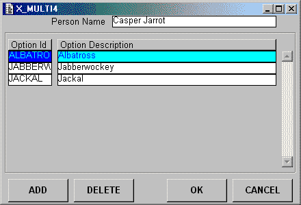
Figure 5 - a simple form design

In Figure 5 the entities are painted with PERSON as the outermost, then PERS_OPT_XREF (with multiple occurrences), and OPTION as the innermost. Only those occurrences of OPTION which have an entry on PERS_OPT_XREF are shown. New occurrences of PERS_OPT_XREF are created either by the user typing in the primary key (if known) or by activating a popup form (a type of picklist) from which a choice can be made. Duplicate entries are automatically rejected by the standard code in the <leave modified key> trigger.
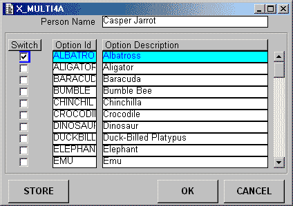
Figure 6 - a more user-friendly design

In Figure 6 the entities are painted with PERSON as the outermost, then OPTION (with multiple occurrences), and PERS_OPT_XREF as the innermost. All occurrences of OPTION are retrieved, and each occurrence contains a checkbox to show if a corresponding occurrence on PERS_OPT_XREF exists or not. All the user has to do to change the contents of PERS_OPT_XREF is change the status of any checkbox. The column labels are actually buttons which will cause the occurrences to be sorted using the values in that column, first in ascending order then in descending order. This type of form is more user-friendly because the user does not have to activate a separate picklist form in order to see what other values on the OPTION entity are available.
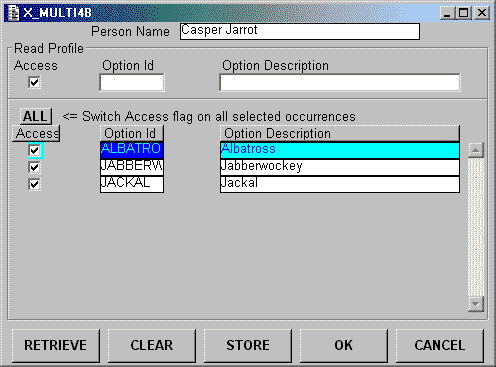
Figure 7 - a more complicated design

The form in Figure 7 is similar to the one in Figure 6, but with the addition of a dummy entity which deals with the specification of read profiles. On initial entry only those occurrences of OPTION which have an entry on PERS_OPT_XREF are shown. The screen contents can be altered by clearing the current contents, entering a new profile, then performing a retrieve. It should be noted that in the profile area the ACCESS field is a tri-state checkbox which means that it has 3 possible settings:
The ALL button will allow the ACCESS flag for all currently selected occurrences to be switched to the opposite value, thus allowing multiple occurrences to be processed with a single mouse click.
The form in Figure 7 would be better than the form in Figure 6 in those cases where the number of occurrences on the OPTION entity were too numerous to be viewed in a single retrieve. The use of the profile area means that different subsets can be selected, viewed and processed at a time.
All the forms shown here were built from component templates which, along with some sample databases and compiled forms, are available for download from my Building Blocks page.
Tony Marston
14th November 2001
mailto:tony@tonymarston.net
mailto:TonyMarston@hotmail.com
http://www.tonymarston.net